Tech Guide

Filter Expressions

Overview

cFosSpeed supports a number of different traffic classes set to different priorities. In effect, this means packets in classes with a higher priority are sent out prior to packets from classes with lower priority – even if low-priority packets arrived before high-priority packets in their respective class queues.

That way, cFosSpeed can prioritize specific packets permitting them to take the “fast lane” and zip past “normal” traffic. This priority system can be modified and expanded by the user with what we call “filter expressions.” These can be used to filter out packets and assign them to a desired traffic class.

Filter expressions consist of a series of “filter rules” that all need to be true for the entire expression to be true. If the entire expression is true, the packet is put into the corresponding class queue.

A list of filter expressions does allow you to filter for several different packets. This list is checked from top to bottom; the first filter expression found to be true (i.e., consisting only of true filter rules) is employed, ending the list traversal.

Packets not matching any particular filter expression are automatically assigned to the “default” class, which is a built-in class with priority 0.

A silly and simple example

A sample list of filter expressions is given below (the output looks like the “spd filter” output described later in this overview). Note that this sample is provided for illustration purposes only; it has no other use.

     0  -p icmp -c fast
     1  -tcp-sport 1234 -tcp-dport 5678 -c special
    

This would mean that if a packet is of IP protocol “icmp”, it would be assigned to “fast” class, ending traversal of the list.

If a packet does not match the first expression, then it will be checked for the second expression. In this case, the latter consists of two rules, which must both be true for the entire expression to be true (a boolean AND).

The “-tcp-sport” entry checks the TCP source port number. Accordingly, for this rule to be true, the packet must have IP protocol TCP and the TCP source port must be 1234.

Then, there is a second rule, which is true if (again) it’s a TCP packet and the TCP destination port is 5678.

Thus, all TCP traffic transmitted from port 1234 to port 5678 would be assigned to “special” class (which doesn’t exist by default).

If neither of the two rules apply to the packet (which should happen fairly often), it is put into “default” class instead.

Filter rules reference

Now let’s go into more detail.

Each rule can be negated by preceding it with a ‘!’ (exclamation mark) or by putting the ‘!’ in between the option name and value (if such a value exists). So it has to be “!-f”, but you could also use “!-p icmp” or “-p !icmp”.

Underlying most rules are one or more implicit assumptions; for instance, -tcp-length assumes it’s a TCP packet after all. These assumptions are listed with each rule. If a packet does not match the assumptions, the rule is false. Note that a rule with a non-matching implicit assumtion is false even if it is negated (by using ‘!’).

That is, a !-tcp-length 0 rule matches TCP packets of any length other than zero, but does not match any non-TCP packet.

If you need to specify a number, you can enter the number either in decimal (just type it in as is) or hexadecimal (prefix it with “0x”) format. For example, 16 and 0x10 both denote decimal number 16.

For some rules, a range of values can be entered. Allowable value ranges are:

num
like “99”.
A single number that must be matched exactly. As usual, the number can be entered either in decimal or hex format.
from:to
like “42:99”.
Range of integers starting and including “from”, while also including and ending with “to”. If “from” is higher than “to”, the two values are exchanged.
:to
like “:99”.
Short for “0:to”; in this example, short for “0:99”.
from:
like “42:”.
Short for “from:0xffffffff”.

What’s more, a list of ranges can be entered for some rules. That is simply a concatenation of several ranges, separated by commas (,). For example, “1:2,3:4” is just another way of writing “1:4”. There must be no space around the comma.

Basic rules

-tx

Transmit. True if the packet is sent. There is no implied assuption with this rule.

We maintain separate lists of filters for both transmit and receive. By using this rule you specify that a filter is only to be put on the transmit list. Since this can’t change in session, the rule is not re-evaluated each time a packet comes in; we call it a “cheap rule”.

-rx

Receive. True if the packet is received. There is no implied assuption with this rule.

Comments of “-tx” rule apply analogously.

-wan
Packet is transmitted on a WAN port (i.e., on NDISWANIP device) in contrast to LAN port. Is always true for cFos. There is no implied assuption with this rule. This rule is “cheap”, too.
-bridged
Packet is transmitted on a LAN port and your modem works as a bridge, not as a router.
That is, the IP subnet is not your own, but your provider’s. There is no implied assuption with this rule. This rule is “cheap” only on a WAN port, since this is always considered bridged.
-eth

The port operates with Ethernet framing.

This is always true for cFosSpeed and always false for cFos. This rule is “cheap” and has no implied assumption.

-ethp protocols

Ethernet protocol number.

This rule has the implied assumption that Ethernet framing is used, i.e., it is always false for cFos.

You can specify a list of ranges for “protocols”. Protocol numbers may be written in decimal or hex.

Some protocol numbers are:

0x800
IP, Internet Protocol version 4
0x806
ARP, Address Resolution Protocol
0x86dd
IP, Internet Protocol version 6

For a more extensive list of protocol numbers see www.iana.org/assignments/ethernet-numbers.

-ppp

The port operates with PPP framing.

This is always true for cFos and always false for cFosSpeed. This rule is “cheap” and has no implied assumption.

Details on PPP can be found in RFC 1661 (The Point-to-Point Protocol), www.ietf.org/rfc/rfc1661.txt.

-pppp protocols

PPP protocol number.

This rule has the implied assumption that PPP framing is used, i.e., it is always false for cFosSpeed.

You can specify a list of ranges for “protocols”. Protocol numbers may be written in decimal or hex.

Some protocol numbers are:

0x21
IP, Internet Protocol version 4
0x2d
Van Jacobson Compressed TCP/IP
0x2f
Van Jacobson Uncompressed TCP/IP
0x57
IPv6, Internet Protocol version 6
0x8021
Internet Protocol Control Protocol
0x8057
IPv6 Control Protocol
0xc021
Link Control Protocol

For a bigger list of protocol numbers see www.iana.org/assignments/ppp-numbers.

-ipv4
IP version 4. True if the packet is IPv4 and basically well-formed.
-ipv6
IP version 6. True if the packet is IPv6 and basically well-formed.
-mp-header

The packet has a Multilink-PPP header.

This rule has the implied assumption that PPP framing is used, i.e., it is always false for cFosSpeed.

Details on PPP Multilink can be found in RFC 1990 (The PPP Multilink Protocol), www.ietf.org/rfc/rfc1990.txt.

-mp-begin

The packet has the (B)eginning fragment bit set in the Multilink header.

This rule has the implied assumption that the packet has a Multilink PPP header, i.e., the rule is always false for cFosSpeed.

-mp-end

The packet has the (E)nding fragment bit set in the Multilink header.

This rule has the implied assumption that the packet has a Multilink PPP header, i.e., the rule is always false for cFosSpeed.

-mp-frag

The packet has in its Multilink header either no (B)eginning fragment bit set, or (E)nding fragment bit set, or both.

This rule has the implied assumption that the packet has a Multilink PPP header, i.e., the rule is always false for cFosSpeed.

-rand prob chance

Pseudo-random number.

The rule returns true if a pseudo-random number between 1 and “prob” (borders included) is <= “chance”. “prob” must be between 1 and 2^32-1, “chance” can even be 0.

The pseudo-random numbers are generated by a comparatively poor generator (LCM style). It will still look “random” enough for packet-loss tests.

Example: This rule will be true in 5% of all cases (statistically):
-rand 100 5

IP header filter rules

Details on the IP v4 header can be found in RFC 791 (Internet Protocol), www.ietf.org/rfc/rfc0791.txt and details on the IPv6 header can be found in RFC 2460 (Internet Protocol, Version 6) www.ietf.org/rfc/rfc2460.txt.

IP header filter rules apply only to IP packets with a correct header and checksum (IPv4 only, IPv6 has no header checksum). These rules work on any IP packet, fragment or not.

-s address-list

Source IP address.

There are several ways to specify “address-list”:

adr
like 1.2.3.4
or 2001:0db8:0000:0000:0000:ff00:0042:8329
or [2001:db8::ff00:42:8329]
This rule matches exactly one address with no wildcarding possible.
adr/netmask
like 1.2.3.0/255.255.255.0
This can be used to specify an “IP subnet”. The match works as follows: If the address that is to be tested AND the “netmask” are equal to “adr”, then there is a match, otherwise not. This works just like IP routing rules.
adr/bits
like 1.2.3.0/24
or 2001:0db8::/64
This is an alternative form of the adr/netmask approach above. Here, “bits” refer to the number of “1” bits, starting at the left of a 32-bit (IPv4) resp. 128-bit (IPv6) number. Thus, for IPv4 “/24” is 24 1-bits and eight 0-bits. In the regular format separated by dots, this would come out as 255.255.255.0 (since 255 is 11111111 in binary code).
adr,adr…
like 1.2.3.0/24,4.5.6.7,8.9.0.0/255.255.0.0
or 2001:0db8::/64,[fe80::1],8.9.0.0/16
You can make a list of any of the above used notations and mix IPv4 and IPv6. Don’t leave any spaces and separate the items with a comma (‘,’).
-d address-list
Destination IP address, where “address-list” has the same format as explained for the -s filter.
-l address-list
Local IP address, where “address-list” has the same format as explained for the -s filter.
The local address is the source address of a sent packet and the destination address of a received packet.
-r address-list
Remote IP address, where “address-list” has the same format as explained for the -s filter.
The remote address is the destination address of a sent packet and the source address of a received packet.
-p protocol

IP protocol, where “protocol” is either a decimal or hex number or one of the following hard-coded names:

ICMP
protocol number 1
HOPOPT
protocol number 0
IGMP
protocol number 2
TCP
protocol number 6
UDP
protocol number 17
IPV6
protocol number 41
IPV6-ROUTE
protocol number 43
IPV6-FRAG
protocol number 44
GRE
protocol number 47
ESP
protocol number 50
AH
protocol number 51
ICMPv6
protocol number 58
IPV6-NONXT
protocol number 59
IPV6-OPTS
protocol number 60
MOBILITY
protocol number 135
-f
IP datagram is not the first fragment (that is, the IP header field “fragmentation offset” is not equal to 0).
-mf
“More Fragments” bit in IP header set.
-fragment
Datagram is not a complete IP frame, but a fragment. That is, either “fragmentation offset” is not 0 or the “More Fragments” bit is set.
-df
“Don’t Fragment” bit in IP header set (IPv4 only, there is no such bit under IPv6).
-tos type-of-service

Type of service.

“type-of-service” can be any decimal or hex number between 0 and 255. Note that TOS is neither used nor supported much any more. For details, see RFC 1349 (Type of Service, www.ietf.org/rfc/rfc1349.txt). See -dscp option below for a modern way of interpreting the TOS field. www.iana.org/assignments/ip-parameters lists common TOS values. Under IPv6 this rule refers to the “traffic class” field of the header.

-dscp dscp-value

Differentialed Services Coding Point, an alternate way of interpreting the TOS field.

“dscp-value” can be a value between 0 and 63 or a range of such values. For details, see RFC 2474 (Differentiated Services, www.ietf.org/rfc/rfc2474.txt). See -tos option above for the traditional (now almost extinct) way of interpreting the TOS field.

-ttl ttl-value

IP header field “Time to live”.

“ttl-value” can be a range of numbers between 0 and 255. See “range” below on how to specify a range.

-length value

Length of the IP datagram or fragment, including the header.

You can specify a range for “value”, which is the length of the packet about to be send. With a fragment, it’s not the length of the reassembled datagram but the length of the individual fragment.

-data-length value

Length of the data portion of an IP datagram, which is the length of the (reassembled) datagram minus the IP header length.

For IPv6, this does not include the HOPOPT, ROUTE, DESTOPTS, MOBILITY and FRAG extension headers. They are not considered part of the “data”.
You can also specify a range for “value”.

-ihl value
Length of the IP v4 header, with values anywhere from 20 to 60 (IPv4 only). Again, you can specify a range for “value”.
-s-mynet
The source address is in your subnet.
-d-mynet
The destination address is in your subnet.
-l-mynet
The local address is in your subnet.
-r-mynet
The remote address is in your subnet.
-s-bcast

The source address is the subnet directed broadcast address (IPv4 only, there is no such concept under IPv6). I.e., if your subnet is 192.168.1.0 and has subnet mask 255.255.255.0, this rule will match on source address 192.168.1.255.

Note that this filter will not match the limited broadcast address 255.255.255.255.

-d-bcast
The destination address is the subnet directed broadcast address. See -s-bcast for more info.
-l-bcast
The local address is the subnet directed broadcast address. See -s-bcast for more info.
-r-bcast
The remote address is the subnet directed broadcast address. See -s-bcast for more info.
-s-iplist list
The source address is listed in the iplist named ‘list’. For more on iplist’s see “IP-range lists”.
-d-iplist list
The destination address is listed in the iplist named ‘list’. For more on iplist’s see “IP-range lists”.
-l-iplist list
The local address is listed in the iplist named ‘list’. For more on iplist’s see “IP-range lists”.
-r-iplist list
The remote address is listed in the iplist named ‘list’. For more on iplist’s see “IP-range lists”.
-ip-opt list
Packet has at least one of the listed IP-options in its header (IPv4 only). The options can be set in decimal or hex and are separated with a comma, like “131,137”. A list of IP-options is here: www.iana.org/assignments/ip-parameters.

UDP header filter rules

Details on the UDP header can be found in RFC 768 (User Datagram Protocol, www.ietf.org/rfc/rfc0768.txt). Note that each UDP header is prefixed by an IP (v4 or v6) header, since UDP needs IP for transmission.

UDP header filter rules apply only to packets with a correct IP header, protocol set to UDP, and correct UDP header checksum. In addition, they must either be unfragmented or the last fragment that completes the reassembled datagram.

-udp-sport ports

UDP source-port number, or a range of several such ports, or a list of ranges (see above on how to specify them).

A UDP connection is identified by the following four values: source IP address, source UDP port number, destination IP address, and destination UDP port number. So, whenever you send a UDP packet from A to B, the packet always contains those four values.

Since these filter rules are only used for outgoing data packets, “source port” always refers to the port number of the connection on your (local) side.

-udp-dport ports

UDP destination-port number, or a range of several such ports, or a list of ranges (see above on how to specify them).

See -udp-sport for more on port numbers.

Since these filter rules are only used for outgoing data packets, “destination port” always refers to the port number of the connection on the remote side.

-udp-lport ports

Local UDP port number, or a range of several such ports, or a list of ranges (see above on how to specify them).

See -udp-sport for more on port numbers.

-udp-lport ports

Remote UDP port number, or a range of several such ports, or a list of ranges (see above on how to specify them).

See -udp-sport for more on port numbers.

-udp-length value

Length of the UDP data portion including the UDP header as mentioned in the UDP header.

Since the UDP header is as well counted in “value”, even the smallest UDP packet possible would have a length of 8. Note that this is different from the concept of -tcp-length (see below).

-udp-prog programnames

Name of the program that sent the datagram.

Note: This only works starting with Windows XP and it only works if the program is running on the same machine as cFosSpeed is (that is, it does not work if cFosSpeed is used on a router and the program is running on a client).

“programnames” can be:

program name
Must be a full file name with extension, but no path (like ftp.exe). Case does not matter. If the program name includes a space, put it in quotes (like “the best.exe”).
@section name
The name of a section in settings.ini that contains names of programs (like @lowprogs with a [lowprogs] section somewhere is settings.ini).
@file/section name
The name of a section in “file”. “file” can be a fully specified pathname or “user.ini” to specify user.ini in cFosSpeed directory. The handling is otherwise like that of “@section” above.
list
A comma delimited form of the above. There must be no spaces before or after the commas. Example: ftp.exe,telnet.exe,”the best.exe”,@lowprogs

See “Managing program names” later on how to manage keys in sections.

TCP header filter rules

Details on the TCP header can be found in RFC 793 (Transmission Control Protocol, www.ietf.org/rfc/rfc0793.txt). Note that each TCP header is prefixed by an IP (v4 or v6) header, since TCP needs IP for transmission.

TCP header filter rules apply only to packets with a correct IP header, and protocol set to TCP. They must be either unfragmented or the last fragment that completes the reassembled datagram.

-tcp-sport ports

TCP source port number, or a range of them, or a list of ranges (see above on how to specify them).

A TCP connection is identified by the following four values: source IP address, source TCP port number, destination IP address, and destination TCP port number. So, whenever you send a TCP packet from A to B, the packet always contains those four values.

Since these filter rules are only used for outgoing data packets, “source port” always refers to the port number of the connection on your (local) side.

-tcp-dport ports

TCP destination port number, or a range of several such ports, or a list of ranges (see above on how to specify them).

See -tcp-sport for more on port numbers.

Since these filter rules are only used for outgoing data packets, “destination port” always refers to the port number of the connection on the remote side.

-tcp-lport ports

Local TCP port number, or a range of several such ports, or a list of ranges (see above on how to specify them).

See -tcp-sport for more on port numbers.

-tcp-rport ports

Remote TCP port number, or a range of several such ports, or a list of ranges (see above on how to specify them).

See -tcp-sport for more on port numbers.

-tcp-length value

Length of the TCP data portion, also know as the “TCP segment.”

In contrast to the concept of -udp-length or -icmp-length, this does not include TCP header length, meaning that the smallest TCP packet possible has a -tcp-length of 0.

-thl value
TCP header length, with values anywhere from 20 to 60. You can also specify a range for “value”.
-tcp-flags mask result

Check for the presence of certain flags in the TCP header.

The value of the TCP flags in the header are ANDed with “mask” and the packet is matched if that equals “result”. Both “mask” and “result” must be specified as a list of flags. Recognizable flags are: FIN, SYN, RST, PSH, ACK, and URG. ALL stands for all six of them and NONE for none.

Examples:
-tcp-flags SYN SYN
means: if the SYN bit is set (regardless of the other bits), then the rule matches.
-tcp-flags ALL SYN
means: if only the SYN bit is set and all others are zero, then the rule is a match.
-tcp-flags SYN,ACK ACK
means: if SYN is not set and ACK is set, we have a match.
-tcp-flags URG,PSH NONE
means: if neither URG nor PSH are set, it’s a match.
-syn
Synonymous for “-tcp-flags SYN,RST,ACK SYN”, meaning it only matches the first packet in the TCP three-way-handshake.
-tcp-prog programnames

Name of the program that sent the segment.

Note: This only works starting with Windows XP and it only works if the program is running on the same machine as cFosSpeed is (that is, it does not work if cFosSpeed is used on a router and the program is running on a client).

To learn how to specify “programnames” see -udp-prog rule.

-tcp-connections range
Number of total TCP connections is in “range”. Half-open connections are counted as well. The number of connections doesn’t need to exactly match either side’s count, since cFosSpeed uses its own TCP connection tracking.
-tcp-opt list
Packet has at least one of the listed options in its TCP header. The comments of “-ip-opt” apply. A list of TCP-options is here: www.iana.org/assignments/tcp-parameters.
-tcp-session value

Packet is part of a TCP connection that is in state “value”. Possible states are:

0
A TCB has been created
1
At least one side has sent a SYN
2
Both sides have sent SYNs
3
Both sides have sent SYNs that have been ACKed: connection established
4
At least one side has sent a FIN
5
Both sides have sent FINs
6
Both sides have sent FINs that have been ACKed: connection closed
7
At least one side has sent a RST
8
At least one side has sent a FIN that has been ACKed: connection half-closed
-tcp-session-dadr value

There is a TCP connection in state “value” between the same source and destination address as this packet.

Possible states are the same as listed under “-tcp-session”.

This rule only implies that the packet is a valid IP packet, but not necessarily TCP.

-tcp-initiated direction

Check which side initiated the TCP connection.

“tx” means that the first SYN was sent from local, “rx” that the first SYN was received from the net.

-tcp-seq range

TCP sequence number (subtracted by the initial sequence number) on the particular TCP connection.

TCP keeps your sent data in sequence. So even if packets get lost, corrupted or out of order on the way from source to destination host, TCP will get it right for you (yeah!). To achieve this, TCP packets have a sequence number, so TCP knows the correct order of them. This sequence number is increased with every byte that is transmitted on the connection.

The filter rule lets you use the sequence number as a means of how many bytes have been transmitted on the connection.

“range” can be a range of numbers.

I.e. “-tcp-seq :500” will only match TCP packets that cover the first 501 bytes in their connection (0 to 500, inclusive).

-tcp-cnt range

TCP packet counter for this particular connection.

This counter is increased by one with each packet sent.

UDP and TCP combo rules

Sometimes you have to specify the same rules for UDP and TCP ports. This can be done by the following combo rules.

The assumptions for UDP and TCP packets each still apply.

-sport ports
If it’s a UDP packet, synonymous for “-udp-sport ports”; if it’s a TCP packet, synonymous for “-tcp-sport ports”. Otherwise, there is no match.
-dport ports
If it’s a UDP packet, synonymous for “-udp-dport ports”; if it’s a TCP packet, synonymous for “-tcp-dport ports”. Otherwise, there is no match.
-lport ports
If it’s a UDP packet, synonymous for “-udp-lport ports”; if it’s a TCP packet, synonymous for “-tcp-lport ports”. Otherwise, there is no match.
-rport ports
If it’s a UDP packet, synonymous for “-udp-rport ports”; if it’s a TCP packet, synonymous for “-tcp-rport ports”. Otherwise, there is no match.
-prog programnames

Name of the program that sent the segment.

Note: This only works starting with Windows XP AND it only works if the program is running on the same machine as cFosSpeed is (that is, it does not work if cFosSpeed is used on a router and the program is running on a client).

To learn how to specify “programnames” see -udp-prog rule.

-l7-prot protnames

Check if packet belongs to a TCP connection resp. UDP pseudo-connection with a certain layer-7 protocol. A list of supported layer-7 protocols is in settings.ini, sections highprots, normalprots, lowprots and lowestprots.

For certain protocols (like IRC, Telnet, file sharing, etc.) there is a further check built in: if the rule is about to match and the class the packet will be queued into is higher than default, then the connection must not be in “bulk mode”. cFosSpeed uses statistics to estimate if the connection is is bulk mode, i.e. if data is being constantly sent in large amounts. If the connection is assumed to be in bulk mode, then the -l7-prot rule does not match. This is to prevent protocols that can be used for both bulk and interactive transfer to clog the high classes if the protocol is in bulk mode. This auto-bulk-detection can be switched off by typing the command “spd gset bulk_detect 0”.

This rule has the implied assumption that layer-7 detection is on, i.e. that global variable l7_detect is 1.

ICMP filter rules

Details on the ICMP for IPv4 header can be found in RFC 792 (Internet Control Message Protocol, www.ietf.org/rfc/rfc0792.txt) and details on the ICMPv6 header can be found in RFC 4443 (Internet Control Message Protocol (ICMPv6) for IPv6, www.ietf.org/rfc/rfc4443.txt). Note that each ICMP header is prefixed by an IP (v4 or v6) header, since ICMP needs IP for transmission.

ICMP header filter rules apply only to packets with a correct IP header, protocol set to ICMP or ICMPv6, and correct ICMP checksum. Such packets must also be either unfragmented or the last fragment that completes the unfragmented datagram.

-icmp-type type – or – -icmp-type type/code

Check for ICMP v4 type and code (if specified).

Both “type” and “code” can be any number between 0 and 255. If you specify no “/” and no code, it will match only on the “type” value. Otherwise, the “code” value must match as well.

You can specify a list of type or type/code as well. Use commas to separate the entries in the list.

-icmpv6-type type – or – -icmpv6-type type/code

Check for ICMPv6 type and code (if specified).

The syntax and semantics for this rule are like -icmp-type.

-icmp-length value

Length of the ICMP data portion, including the ICMP header. This is the IP v4 or v6 datagram length minus the IP header length.

Again, “value” can also be a range of values.

VLAN rules

Details on VLAN can be found in IEEE 802.1Q (e.g. on Wikipedia).

The VLAN rules (except -is-vlan) only apply if the packet has a VLAN header at all.

-is-vlan
Matches if a packet has a VLAN header.
-vlan-prio range
VLAN packets have a 3 bit priority field (i.e. the priority is 0-7). If this VLAN priority is in “range”, this rules matches.
-vlan-id range
VLAN packets also have a 12 bit ID field (i.e. 0-0xfff or 0-4095). If the ID is in “range”, this rule matches.

Standard rules

cFosSpeed ships with five traffic classes, called “highest”, “higher”, “high”, “low” and “lowest”. To assign traffic to these classes, we have combined sensible rules into mega-rules.

If you remove the standard rules, you will most likely disable or damage the traffic-shaping operation of cFosSpeed. So, it’s an excellent idea to leave them in place and just add your own rules below these rules!

-highest

This feeds packets to the “highest” class.

All cFosSpeed pings are matched by this rule.

-higher

This feeds packets to the “higher” class.

All TCP ACKs are matched by this rule. ACK is an empty TCP packet with no RST or FIN set.

-high

This feeds packets to the “high” class.

This rule matched all (by default) prioritized traffic: ICMP, DNS and NTP (on UPD), FTP command, POP, IMAP, Telnet, SSH, HTTP, HTTPS (on TCP).

-low
This feeds packets to the “low” class.

Traffic Shaping and other Internet tuning methods

Broadband users in particular want to get the absolute max out of their connection. But even narrowband users may benefit from Internet tuning on their low-speed connections.

What tuning methods are there?

Registry-Tweaks

An entire line of so-called “registry-tweak” programs has sprung up based on the assumption that changing various Internet protocol parameters may boost data-transfer speed. In essence, what such programs do is simply change the values of certain parameters rather than have the user edit the corresponding registry entries manually. Typically, the following parameters are thus adjusted:

  • MTU/MSS:
    Transmission of each packet entails a certain packet overhead, which is always the same – regardless of what size the transmitted packet may be. Thus, sending out packets that are as large as possible would seem to be one probable way to cut back on overall overhead. For instance, a TCP/IP packet sent via DSL/PPPoE has an overhead of 48 bytes (i.e., almost 10 percent for a 500-byte packet). If no value for Maximum Transfer/Transmission Unit (MTU) is specified in the registry, TCP will determine packet size itself through a process called “Path MTU Discovery.” It will do so in such a manner that packets sent will always be of the largest size that can still be handled by all intervening transmission nodes. For DSL/PPPoE, maximum MTU is 1,492 bytes, which corresponds to an overhead of approximately 3 percent. This value really doesn’t need to be set, since Windows already maximizes it through Path MTU Discovery. MSS usually equals MTU-40.
  • TcpWindowSize:
    This parameter controls the maximum number of bytes the remote TCP may send before an acknowledgment must be received. Lacking such acknowledgment, the sender is forced to wait, thus resulting in dramatic drops in transfer rate. Unless the user specifies otherwise, Windows determines the value for this parameter based on packet size (12 * MSS). The greater the latency, the larger the TcpWindowSize needs to be to avoid having the sender wait. Thus, assuming a connection speed of 1,024 kbit/s and 150ms of ping time to server, TcpWindowSize must at least be 2,000 bytes. Should further delays occur, even that wouldn’t suffice anymore. This is why a lot of tuning programs tend to jack TcpWindowSize up inordinately. The problem is that while running an upload, the upload competes with acknowledgments for available bandwidth, meaning the transfer rate will plummet nevertheless. Furthermore, huge TcpWindowSize does also increase latency, which can quickly turn VoIP or online gaming into an exercise in frustration. For instance, at a TcpWindowSize of 64k or higher, latency will rise to more than 400ms, which is absolutely unacceptable for VoIP.
  • TTL:
    This value indicates how often any given packet may be passed on from node to node until it reaches its destination. Changing this value has no appreciable effect whatsoever on transfer speed. Can you spell “placebo software?”
Traffic Shaping

So, in a nutshell, some registry tweaks may sometimes yield greater speed (though often at the cost of significantly higher latency).

Traffic Shaping is then the next logical step in improving data-transfer speed without sacrificing performance elsewhere. It works by sorting data packets according to importance prior to sending them, thereby ensuring all time-critical data are being sent out first. TCP acknowledgments, for example, are highly prioritized so that they are always received in time, which means download data can be transmitted without interruption.

However, the more data are transmitted simultaneously, the more data congestion will likely occur. Therefore, effective Traffic Shaping should ensure not too much data are being sent simultaneously, as this also tends to affect ping times and VoIP speech quality. The more protocols Traffic Shaping can distinguish, the more responsively a system will perform while multiple applications are being run on it at the same time. For instance, Traffic Shaping can be used to accelerate surfing speed by having the corresponding DNS requests prioritized. FTP command, Telnet, SSH and similar protocols can also be prioritized in this fashion.

Since Traffic Shaping boosts transfer rates by reducing latency, it does yield higher speed irrespective of how much bandwidth may be available. This is especially valuable seeing how latency problems during simultaneous use of multiple Internet connections cannot be compensated for by additional bandwidth.

ACK filtering

During each download, acknowledgments take up about 5 percent of the available download bandwidth in upstream direction. The problem here is that upstream bandwidth is much lower than downstream bandwidth for ADSL and broadband cable. This also means there may not be enough upload bandwidth left to achieve full download speed, not to mention that it is always desirable to have some upstream bandwidth available for other uses. For this reason, ACK filtering reduces the size of acknowledgment packets as much as possible without decreasing download rates. In this manner, the bandwidth needed for handling acknowledgments can often be cut in half.

Data compression

It is always nice to be able to compress user and/or protocol data. For Web servers, so-called “GZIP compression” lends itself particularly well to this. With it, the text on Web pages can be compressed to about half the original size prior to transmission. Leading Web browsers like the Internet Explorer or Mozilla Firefox do support GZIP compression. The Web server is also smart enough to send uncompressed data instead when dealing with old browsers that do not support GZIP. Therefore, there is to our knowledge no drawback to using GZIP. Unfortunately, it can only be activated by a Web server’s administrator.

Modems and ISDN make use of V.42bis and Stac data compression, respectively. Both reduce the amount of text data transmitted between dial-in node and modem or ISDN board by roughly one half. Thus, these compression methods could conceivably double transfer speed in both direction for types of data (like text) that can be compressed well. But because image files account for most of the data servers must transmit for today’s Web sites, our experience has generally been that this kind of compression makes very little difference. The same is true if a server is sending data already compressed in GZIP format.

In contrast, VJ compression (also known as IP-header compression) does not minimize the size of user data but only that of protocol data. Assuming a standard narrowband packet size of 576 bytes, this can effectively cut TCP/IP header size from 40 to 3 bytes, resulting in a reduction of packet overhead from approximately 7 to 0.5 percent. While this is of great interest for low-speed modem and ISDN connections, it is very rarely if ever used for broadband connections. DSL and cable providers would much rather sell their clients more bandwidth.

Download accelerator

Many servers permit downloads at no more than a predefined maximum download rate. The idea behind most download accelerators is to circumvent this by downloading a file in several segments at the same time through multiple connections to the same server. This does indeed often lead to higher download rates.

Web accelerator

The ability to use cell phones for wireless (yet typically very slow) Internet access has dramatically increased the demand for having Web-page data compressed prior to transmission. Such precompression might also be useful for modem or ISDN connections. Providers of Web accelerator software maintain their own servers with broadband connections to the Internet. These are needed to first load the desired data, compress it, and then send it through the bottleneck of the modem, ISDN or radio-network connection.

But due to the large image files involved, the gain thus yielded by conventional compression methods can only be marginal at best. This is why more and more Web accelerators have begun to manipulate image data as well. To make some headway there, images are usually reduced in color depth and resolution. Given the small size of their displays, this poses little if any problem with respect to cell phones. But on desktop computers it may well result in a clearly discernible loss in quality for desktop applications.

Installation of the respective browser add-on is required for using the services of a Web accelerator – as is in most cases payment of a monthly fee or surcharge. Using web accelerators does yield little appreciable gain in speed on broadband connections. Countervailing this is a possible increase in latency, since the Web accelerator is interposed between server and client.

Faster Connection

Switching to a rate plan that gives you higher connection speed is still the safest way to improve bandwidth and thus achieve better data transmission rates. This as such won´t improve ping times though. And neither will it prevent downloads from slowing dramatically, even stalling altogether, when data is being uploaded at the same time. That’s why it is ideal to combine any bandwidth upgrade with Traffic Shaping technology.

Brief Comparison of Tuning Methods:

Tuning MethodsProsCons
Registry Tweakspotential gain in speed
may be available for free
high latency
Traffic Shapinghigher speed
lower ping times
–
ACK Filterhigher speed–
Data compressiongain in speed
(mostly for texts)
–
Download-accelaratorpotential gain in speed–
Web-accelaratorfaster surfing speedhigher latency, reduced quality
Faster Connectionfaster speed–
 

cFosSpeed offers both – Traffic Shaping and ACK-filtering. In addition, it automatically optimizes MTU and TcpWindowSize!

Links

TCP/IP-Tuning
@ heiseNetze 
(german)

RWIN Expansion

Benefits of activating “Automatic RWIN expansion”

See how cFosSpeed improves Internet Explorer downloads

See how cFosSpeed improves Mozilla Firefox downloads

See how cFosSpeed improves Cygwin SCP downloads

YouTube playlist with submissions of award winners

See how cFosSpeed improves Cygwin SCP downloads

Technical background

TCP Auto-Tuning measures the RTT of connections at the beginning and if data is sent. For connections with only received data and no data to send, this measurement can become inaccurate, so the resulting RWIN remains too small. You can easily verify this behavior with a fast Internet connection and high latency, for example a 50Mbit/s connection from Europe to America or a mobile broadband connection.

Results of cFosSpeed RWIN-Expansion-Award 2012

A lot of users don’t get the maximum speed available for their Internet connection. In many cases the TCP Auto-Tuning of Windows 7/ Windows Vista cannot use the full download speed. In other cases the downloading programs are not written for today’s high speed connections. cFosSpeed’s RWIN expansion now accelerates these downloads by dynamically expanding the receive window size of the TCP connection to a value suitable for the current connection. This leads to unexpected speed improvements!
For example, we could double the download speed with Internet Explorer and nearly triple the speed of mobile UMTS downloads.

To demonstrate these dramatic speed improvements, we (with the help of our users) compiled a list of scenarios in which the new cFosSpeed RWIN Expansion achieves these huge speed improvements.

Technical Reference

This reference is divided into several sub-pages:

That’s it.

Have fun shaping your traffic!

Great Voice-over-IP (VoIP) speech quality

Not only is minimal latency absolutely essential for Voice-over-IP, it is the single most important factor in improving speech quality.

Traffic Shaping technology does keep ping times low and transfer rates consistently high at the same time.

RTP detection integrated in cFos and cFosSpeed permits prioritizing VoIP and other live streams (like conference channels).

Its prioritization can be adjusted under Protocol or Program Settings. Should a particular live stream not be recognized, you can prioritize the respective program by name.

Please note that some programs (like VoIPBuster, IxChariot) only use RTP but not the corresponding RTCP connection. For these, you should deactivate strict RTP verification in the settings.

Dropouts During Download:

VoIP connections usually suffer from dropouts when downloads are simultaneously run at full speed. Thanks to their integrated RX shaping, cFos and cFosSpeed help avoid this problem by keeping ping times consistently low.

Please note that some programs (like VoIPBuster, IxChariot) only use RTP but not the corresponding RTCP connection. For these, you should deactivate strict RTP verification in the settings.

Skype:

Skype employs a proprietary encrypted protocol that cannot be detected by a Layer-7 analysis without considerable effort. To allow users to prioritize Skype nevertheless, we have entered it in our program list.


VoIP via Router Prioritization:

Some routers (like the Fritz!Box) are equipped with phone jacks. If a jack is used, all VoIP data will be transmitted directly to the Internet bypassing cFosSpeed entirely. Such routers may restrict the available bandwidth when a VoIP call is made causing a negative impact on Traffic Shaping performance. Therefore we recommend making VoIP calls from your computer, not the router, to allow cFosSpeed to detect and prioritize them.

Optimizing Connection Settings:

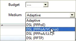
You can specify exactly what transfer medium you use under Connection Settings. The more information about a connection is available to cFos or cFosSpeed, the better ping times will be. Default is “Adaptive”. But if you were for instance using a DSL connection, you should select the appropriate DSL standard or protocol as your medium.

Favor Ping:

VoIP Software in use with cFosSpeed

  • 1&1 SoftPhone
  • Counterpath Bria
  • Counterpath Eyebeam
  • Counterpath X-lite Pro
  • ekiga SIP voip software
  • FreeCall
  • Gizmo Project
  • GlobalIP Ninja Lite
  • Google Talk
  • iPhone
  • Ixia IxChariot
  • SIPPS or AOL Softphone
  • Skype Internet Telephony
  • SparVoip
  • Teamspeak
  • Ventrilo
  • VoipBuster
  • VoipCheap
  • Web.de Freephone
  • WOIZE
  • Xfire
  • X-Lite
  • X-PRO
  • Yahoo Messenger

Measurements with IxChariot

We tested our software using IxChariot (a network performance testing tool provided by Ixia) to evaluate the benefits of cFosSpeed Traffic Shaping. For this purpose, we monitored the VoIP parameters with IxChariot while performing multiple uploads.

You can easily notice that without cFosSpeed normal VoIP communication is not possible during an upload, but it proceeds almost unaffected when using cFosSpeed.

In particular, you can see the MOS value (https://en.wikipedia.org/wiki/Mean_opinion_score) decreasing rapidly towards 1 after starting the upload. This means that the connection has become unusable for voice transfer. When using cFosSpeed the value doesn’t decrease – the speech transmission retains its high quality.

The delay is a crucial part of the MOS value. Using cFosSpeed keeps the increase of this delay within bounds, whereas it raises up to 700 milliseconds when not using cFosSpeed (red graph).

hrPing - High-precision ping utility

Why another Ping utility?

Many Ping utilities are already available, one is even released with Windows itself, called Ping. But hrPing has some advanced features other Pings have not.

In short:

  • Graphical display of ping results
  • Uses high resolution timers, so ping times are accurate to the usec
  • Can ping as well with UDP packets or ICMP timestamp messages
  • Times and handles ICMP error replies as well
  • Can have multiple pings “in-flight”, no need to wait for a reply before sending the next ping
  • Improved statistics
  • Size sweep: Send increasing packet sizes
  • Can show only a summary of results
  • Is a Traceroute and a Pathping as well

You can do much more with hrPing than with Windows Ping.

More text, please.

Like every Ping, hrPing sends “ICMP Echo Request” packets to the remote computer and listens to the matching “Echo response” packets. What’s more, hrPing can send UDP packets and ICMP timestamp packets as well. Not all packet types pass all firewalls and networks equally easy. With hrPing you have the possibility to vary. (-M and -u switches)

What’s more, hrPing times the round trip delay in microseconds (1/1000 msec). This is usually done by using the Windows’ “Performance Counter” which has a resolution of some MHz. You can even ask hrPing to use the CPU’s “Time Stamp Counter” which is incremented with the CPU’s clock cycle. You can’t get any more accurate with standard PCs today!

The next thing Windows Ping can not do is send more than one ping packet at a time. Windows Ping always sends one packet, waits for the reply, then prints its output line, repeat.

hrPing sends out one ping packet every x milliseconds (you can adjust this time with the -s parameter) while listening for incoming replies and printing the output if there is any.

The reason why you should like this is easy: with broadband you often have a delay of some 40 msec, while the upstream bandwidth of the whole connection is some 500 kbytes/sec. So, with a “standard” ping packet of 60 bytes (IP header + ICMP header + ping payload) you can send thousands of packets before you get the first reply. If you want to test line conditions, throughput, etc. this “overlapped” way of sending is really helpful.

Plus, hrPing has much better statistics than Windows Ping. You get the round trip times for ICMP error message replies as well! This way you can e.g. monitor the delay of a TTL exceed. hrPing counts the replies and error messages separately, so the global statistics don’t mess up one another. Plus, for the statistically inclined, hrPing calculates the standard deviation as well, to show you how much the values “jiggle”. hrPing shows you the standard deviation of the timings as well as the average times.

hrPing displays the IP identification field of the replies and thus makes it possible to do “silent load measurements”; see german c’t magazine 23/2003, p. 212 for details. (-I switch)

When sending a lot of packets hrPing’s “Summary mode” comes in handy: it will suppress the printing of each reply on its own line, but instead print a summary for all replies so far and a summary for the last 10 seconds (time can be adjusted). This lets you keep a nice overall view. (-y switch)

Is there more? Yes: hrPing can send out pings with increasing sizes: the “Size Sweep” function, where after each send, the size is increased until it reaches a maximum, then reset. Plus, we do some math when processing the replies and estimate the line speed, if the data is conclusive enough. (-l and -L switches)

Ah, one more thing: hrPing is a traceroute (-r switch) and a pathping (-p switch) as well 🙂

There’s a lot more goodies hidden in hrPing, just use it and you will find out about small but useful features.

And this is how to use it:

hrPING [<options>] <host>

<host> may be the IP address or the hostname. In the latter case the name will be resolved to its address at the beginning of the ping loop.

There are a couple of options that let you specify the data you’re sending:

-fSet Don’t Fragment flag in packet.

Set the “Don’t fragment” bit in the IP header of the PING packet. Default is not set.

-i TTLTime To Live.

Set the “Time To Live” value in the IP header of the PING packet. Default is 255.

-v TOSType Of Service.

Set the “Type Of Service” bits in the IP header of the PING packet. Default is 0. It is possible that Windows erases or overwrites this field when sending the packet. Furthermore, TOS is deprecated nowadays. hrPing will use IP_HDRINCL option to set TOS.

-l sizeSend buffer size (ICMP payload size).

How may bytes payload should be send? Remember that each packet is of the form: IP header (20 bytes) + ICMP header (8 bytes) + payload. You may only specify the payload size. Minimum is 0, maximum is 64k-1-20-8, i.e., 65507 bytes. Default is 32 bytes.This works for UDP mode as well, but not for ICMP timestamp mode. There the ICMP length is always 10 bytes.

-l s1[:s2[:i]]Size sweep: send buffer size from s1 to s2 step i

With this syntax hrPing will start sending a payload of s1 bytes, increase the payload by i bytes for each send (if i was set, otherwise increment by 1) until s2 is reached or exceeded and then restart with s1 bytes. This switches the correlation calculation on that tries to see if there is a correlation between the size of the packet you send and the time it takes for a reply.

-L sizeTotal IP datagram size (ICMP payload size + 28).

Same as the above, only that this size here is the size for the total IP datagram.

-L s1[:s2[:i]]IP datagram size (payload size + 28, default 60) [with sweep]

Analogue as above for -l s1[:s2[:i]]

-MSend ICMP timestamp requests

This will send out ICMP timestamp requests and print ICMP timestamp replies. In the reply there is the send time off the other side in milliseconds, so it’s possible to distinguish between delay that was caused sending and delay that was caused when receiving. These numbers have only millisecond resolution. To synchronise clocks hrPing will calculate the clock offset from the first ICMP timestamp reply, assuming that half of the delay came from each direction.

-u [port]Send UDP packets (port 7 by default)

You can send UDP packets as well. This causes UDP packets to be send to and from port port. Hopefully, the other side has no UDP port under that port number and will reply with a “port unreachable” message, which will be counted as a proper reply.

Options that allow you to specify how hrPing operates:

-tPing the specified host until stopped.

Loop forever. You can abort hrPING any time with CTRL-C or CTRL-Break. Unlike Windows PING, hrPING will still print the statistics gathered so far when you abort. CTRL-C waits for some time for replies still to come in before it aborts. If you are fed up with waiting, press Ctrl-C 5 times. Ctrl-Break just prints the statistics, but doesn’t abort. That’s nice in quiet mode or with many replies.

-n countNumber of echo requests to send.

Specify the number of PING packets to send. Default number is 4. For traceroute or pathping modes (see below) this specifies the number of pings per hop. For tracerroute mode, the default number is 3.

-w timeoutTimeout in milliseconds to wait for each reply.

Maximum timeout to wait for a reply. This time applies when hrPing is waiting for the last replies to come in. Furthermore, hrPing will even count a reply as timeouted if it took too long. Default is 2000 milliseconds.

-s timeInterval in milliseconds between packets.

This is the number of milliseconds between sending of two PING packets. hrPINGwill try to stick to this number quiet accurately. If sending took a little longer for one packet it will send out the next packet a little earlier. Default is 500 milliseconds. (You can use decimals for a very fine grained interval: -s5.4 will send a packet every 5400 microseconds on average.)

-c [num]Concurrent sending of up to num pings at a time (default 1)

Try to keep a maximum of num pings in transmission without a reply. When either a reply comes in or a timeout occurs, send more pings, so num pings are again in flight.-c (without a number) effectively turns off overlapped send/receive, since a second ping is only sent after a reply to the first or an timeout. This, together with the -w option make hrPing behave like Windows’ ping.

-r [count]Be a traceroute (do count pings each hop, default 3)

hrPing contains a traceroute utility! It works almost the same as Windows TRACERT, except that you can specify how many packets are sent per hop, default is three. By default, IP addresses are not resolved to names. Use -a to do that.

-a [hop]Resolve addresses to names for traceroute (start at hop)

This tries to resolve the IP addresses into DNS names. If you specify hop hrPing will not try to resolve the first hop-1 hops, since they are often not resolvable and it only costs time to try (and who has time nowadays?)

-pTrace path to destination, then ping all hops on path

Do a path ping: work like traceroute to get the adresses on the path to a given destination, then ping each of them individually (-u and -M honoured as well as other options that make sense (-l, even with size sweep, -c, -s, -w, etc). At the end, print some statistics for all hops on the path.

And some options control the output:

-licShow public license and warranty.

We need you to accept the software license. This is done the first time you start hrPING. If you want to re-read it, use this option.

-fwhelpPrint firewall help text

Remarks on how to set up the Windows firewall to let hrPing’s packets pass.

-F fileLog output into file as well, even if -q is set

All output is logged to file file as well as to the screen. If -q options are set, all output goes to log file, even if it’s not printed to the screen.

-TPrint timestamp in front of each line

Preceed each line of output with a timestamp of the form
“2012-05-22 18:19:53.508: “

-q[r|e|t]Be quiet (-qr=no replies, -qe=no errors, -qt=no timeouts)

Be quiet. Use -qr to not print replies, -qe to not print IMCP error messages or -qt not to print timeouts.

-y [sec]Print summary of the last sec secs (default 10)

Be quiet, but print a summary of all packets (with counts and statistics) and one of packets of the last sec seconds. Useful with small -s send delays or long sends (-t or high -n).

-g -G 

Show graph of the ping times. To do that, grping.exe is started. More on that later on. Use -gg to close graph on hrping exit. Use -G to utilize a already running grping.exe.

-? -hHelp

Prints a help screen, -?? or -hh prints an even longer one.

And then, we have options for the connoisseur:

-I idSet ICMP id field to id

Set the “Identification” IP header field to the value specified. It is possible that Windows erases or overwrites this field when sending the packet.

-W“warm up” with one uncounted echo request at beginning

If specified, hrPING will send one uncounted ping before all others. This “warm up” is useful with some firewalls that somehow cause the first block to be much slower than the following ones. -s, -w apply.

-AAbort after the first echo reply (-AA => or error)

Loop as long as there are no proper replies (or even error messages if -AA).

-HUse IP_HDRINCL socket option (default for UDP or with TOS)

With this option set, hrPing sets up his IP headers for send itself, otherwise Windows does it. -H is selected automatically with -u or -v, because it doesn’t work otherwise.

-E fileStop pinging if file exists

This is nice for batch files or for coordinating with a background job. hrPing will loop as long as usual (i.e. depending on -t or -n options), but will furthermore check for the existence of file. If file comes into existence, hrPing will exit the loop.

-diagDiagnose your connectivity: send different packet types

Send all kinds of different packets (ICMP echo, ICMP timestamp, UDP) with high and low TTL to the destination and see if we get an answer. That might be useful to check what is coming through your firewall or ISP.

-KWait for any key press when done

Useful if hrPing is started from Windows Explorer.

-qr timeSuppress all replies under time msec

Suppress all reply outputs under time msec, but write them still to the logfile, if provided.

-O ofsSet time offset in msec for timestamp mode

Specify the time offset between your time and the receiver’s time by hand, otherwise hrPing will do that on the first reply.

-DPrint debug info

Well, somewhere debug info is printed. I don’t want to be too specific. Actually, it’s a secret. 🙂

You can mess around with the timer, if you want:

-perfcntUse performance counter (default)

Use the performance counter of Windows. Usually, it’s pretty accurate (some MHz). That’s the default.

-tscForce RDTSC usage.

hrPING automatically decides if it uses the CPU’s timestamp counter (TSC) or the operating system’s performance counter for timings. On some CPU’s the TSC is not reliable, since it doesn’t tick at the same speed all the time. On multiprocessor systems, not all TSC have to tick exactly in sync. In almost all cases, hrPING will use the performace counter. If you want to force TSC usage, use -tsc, but hrPing will only use the TSC if it thinks it’s accurate.

-mmtimeUse multimedia timer; not very accurate

Use Windows’ multimedia timers. They should be at least accurate to the msec.

-tickUse Windows GetTickCount; very inaccurate!

Use the standard Windows timer. That usually has a resoltion of 15 msec or so. Berk!

-precMeasure timer precision

Not sure how accurate the timer is? Measure it!

Return codes:

For ping mode:

0
All sent pings were answered with their proper replies.
1
All sent pings were answered with their proper replies or ICMP error messages.
2
At least some pings were answered with either their proper replies or ICMP error messages.
3
No replies at all.
9
Error.

For traceroute mode:

0
Reached destination
2
At least some pings were answered with either their proper replies or ICMP error messages.
3
No replies at all.
9
Error.

Now a test run:

Ping us:

C:\> hrPING www.example.com
This is hrPING v5.00 by cFos Software GmbH -- http://www.cfos.de

Source address is 192.168.2.106; using ICMP echo-request, ID=cc09
Pinging www.example.com [123.45.67.89]
with 32 bytes data (60 bytes IP):

From 123.45.67.89: bytes=60 seq=0001 TTL=55 ID=becc time=42.803ms
From 123.45.67.89: bytes=60 seq=0002 TTL=55 ID=becd time=43.768ms
From 123.45.67.89: bytes=60 seq=0003 TTL=55 ID=bece time=44.842ms
From 123.45.67.89: bytes=60 seq=0004 TTL=55 ID=becf time=43.449ms


    Packets: sent=4, rcvd=4, error=0, lost=0 (0.0% loss) in 1.546366 se
    RTTs in ms: min/avg/max/dev: 42.803 / 43.715 / 44.842 / 0.737
    Bandwidth in kbytes/sec: sent=0.155, rcvd=0.155

You see that hrPing numbers the packets in ascending order. The sequence numbers of the replies are listed (if there are out-of-sequence packets, hrPing will write “SEQ=” instead of “seq=”, so you notice).

Notice the times in microseconds (milliseconds with 3 decimals)

Furthermore, we see the TTL, which is the TTL of the sender, minus the number of hops the packet took to come here. I guess TTL was initially set to 64, so it took the packet 10 hops to come here (64-55+1=10, TTL is only decremented on forward, not on the first send).

Plus, hrPing prints the number of bytes in the received packet and the IP identification field.

Please also notice the statistics with average and standard deviation (which is a measure of how wide the data points are spread out. So 4, 6, 4, 6 has a smaller deviation than 1, 9, 1, 9, even though the average is the same).


Now let’s look at a second test run:

Try to ping us:

C:\> hrPING -i1 www.example.com
This is hrPING v5.00 by cFos Software GmbH -- http://www.cfos.de

Source address is 192.168.2.106; using ICMP echo-request, ID=140d
Pinging www.example.com [123.45.67.89]
with 32 bytes data (60 bytes IP), TTL 1:

From 192.168.2.1: TTL count exceeded; bytes=56 seq=0001 TTL=64 ID=33b7 time=0.990ms
From 192.168.2.1: TTL count exceeded; bytes=56 seq=0002 TTL=64 ID=33b8 time=1.237ms
From 192.168.2.1: TTL count exceeded; bytes=56 seq=0003 TTL=64 ID=33b9 time=0.578ms
From 192.168.2.1: TTL count exceeded; bytes=56 seq=0004 TTL=64 ID=33ba time=1.041ms


   Packets: sent=4, rcvd=0, error=4, lost=0 (0.0% loss) in 1.514205 sec
   RTTs in ms: min/avg/max/dev: 0.578 / 0.961 / 1.237 / 0.239
   Bandwidth in kbytes/sec: sent=0.158, rcvd=0.147

Notice that this is a list of ICMP error messages, yet there are still the sequence numbers and round-trip-times listed.


Measure the delay of your connection:

We use the smallest ping available and we use the shortest route available. We could use traceroute mode to find the first hop and ping that one. But experience shows that the hops often don’t answer to pings. So we use a trick: we send out packets with TTL 2: they will be bounced on the first external hop, since hop 1 is my internal router (use TTL 1 instead if you are directly connected to the Internet). (The trick is not new, this is how traceroute works.)

C:\> hrping -i2 -l0 www.example.com
   This is hrPING v5.00 by cFos Software GmbH -- http://www.cfos.de

   Source address is 192.168.2.106; using ICMP echo-request, ID=a40e
   Pinging www.example.com [123.45.67.89]
   with 0 bytes data (28 bytes IP), TTL 2:

   From 217.0.119.53: TTL count exceeded; bytes=56 seq=0001 TTL=254 ID=0000 time=17.168ms
   From 217.0.119.53: TTL count exceeded; bytes=56 seq=0002 TTL=254 ID=0000 time=16.634ms
   From 217.0.119.53: TTL count exceeded; bytes=56 seq=0003 TTL=254 ID=0000 time=16.740ms
   From 217.0.119.53: TTL count exceeded; bytes=56 seq=0004 TTL=254 ID=0000 time=16.342ms

   Packets: sent=4, rcvd=0, error=4, lost=0 (0.0% loss) in 1.529537 sec
   RTTs in ms: min/avg/max/dev: 16.342 / 16.721 / 17.168 / 0.296
   Bandwidth in kbytes/sec: sent=0.073, rcvd=0.146

So, the minimum delay seems to be some 16.3 ms. If you increase the number of tries you might find an even smaller delay, but it’s not very likely it will shrink a lot more:

 C:\> hrping -i2 -l0 -n1000 -q -s20 www.example.com
   This is hrPING v5.00 by cFos Software GmbH -- http://www.cfos.de

   Source address is 192.168.2.106; using ICMP echo-request, ID=040b
   Pinging www.example.com [123.45.67.89]
   with 0 bytes data (28 bytes IP), TTL 2:

   Packets: sent=1000, rcvd=0, error=1000, lost=0 (0.0% loss) in 20.001239 sec
   RTTs in ms: min/avg/max/dev: 15.501 / 16.181 / 19.551 / 0.547
   Bandwidth in kbytes/sec: sent=1.399, rcvd=2.799

So, the real minimum seems to be around 15.5 ms. We might want to run hrPing all the time to see how well our line is. We can do that and instruct hrPing to be silent and only display a summary:

 C:\> hrping -i2 -l0 -t -y www.example.com
   This is hrPING v5.00 by cFos Software GmbH -- http://www.cfos.de

   Source address is 192.168.2.106; using ICMP echo-request, ID=1807
   Pinging www.example.com [123.45.67.89]
   with 0 bytes data (28 bytes IP), TTL 2:

  Total:
     Packets: sent=85, rcvd=0, error=85, lost=0 (0.0% loss) in 42.042626 sec
     RTTs in ms: min/avg/max/dev: 15.815 / 18.558 / 34.122 / 5.022
     Bandwidth in kbytes/sec: sent=0.056, rcvd=0.113

      Last 10 seconds:
     Packets: sent=20, rcvd=0, error=20, lost=0 (0.0% loss) in 9.531548 sec
     RTTs in ms: min/avg/max/dev: 16.040 / 23.758 / 34.122 / 7.203
     Bandwidth in kbytes/sec: sent=0.058, rcvd=0.117
   [Aborting...]
   Packets: sent=85, rcvd=0, error=85, lost=0 (0.0% loss) in 42.042626 sec
   RTTs in ms: min/avg/max/dev: 15.815 / 18.558 / 34.122 / 5.022
   Bandwidth in kbytes/sec: sent=0.056, rcvd=0.113

This will continue to show a summary (to end it I pressed Ctrl-C). The summary shows that we had an increased ping time in the last 10 seconds. This is no wonder, since I ran an upload at the same time.

What is my line speed?

hrPing has this nice size sweep feature. Let’s try it:

 C:\> hrping www.example.com -l0:1400:96 -n20 -s20
   This is hrPING v5.00 by cFos Software GmbH -- http://www.cfos.de

   Source address is 192.168.2.106; using ICMP echo-request, ID=e80d
   Pinging www.example.com [123.45.67.89]
   with 0-1400 bytes data (28-1428 bytes IP):

  From 123.45.67.89: bytes=28 seq=0001 TTL=55 ID=bf45 time=43.591ms
   From 123.45.67.89: bytes=124 seq=0002 TTL=55 ID=bf46 time=42.699ms
   From 123.45.67.89: bytes=220 seq=0003 TTL=55 ID=bf47 time=44.006ms
   From 123.45.67.89: bytes=316 seq=0004 TTL=55 ID=bf48 time=43.198ms
   From 123.45.67.89: bytes=412 seq=0005 TTL=55 ID=bf49 time=44.212ms
   From 123.45.67.89: bytes=508 seq=0006 TTL=55 ID=bf4a time=43.859ms
   From 123.45.67.89: bytes=604 seq=0007 TTL=55 ID=bf4b time=44.744ms
   From 123.45.67.89: bytes=700 seq=0008 TTL=55 ID=bf4c time=45.763ms
   From 123.45.67.89: bytes=796 seq=0009 TTL=55 ID=bf4d time=44.257ms
   From 123.45.67.89: bytes=892 seq=000a TTL=55 ID=bf4e time=46.415ms
   From 123.45.67.89: bytes=988 seq=000b TTL=55 ID=bf4f time=46.215ms
   From 123.45.67.89: bytes=1084 seq=000c TTL=55 ID=bf50 time=45.993ms
   From 123.45.67.89: bytes=1180 seq=000d TTL=55 ID=bf51 time=46.744ms
   From 123.45.67.89: bytes=1276 seq=000e TTL=55 ID=bf52 time=46.761ms
   From 123.45.67.89: bytes=1372 seq=000f TTL=55 ID=bf53 time=47.214ms
   From 123.45.67.89: bytes=28 seq=0010 TTL=55 ID=bf54 time=43.284ms
   From 123.45.67.89: bytes=124 seq=0011 TTL=55 ID=bf55 time=43.345ms
   From 123.45.67.89: bytes=220 seq=0012 TTL=55 ID=bf56 time=44.738ms
   From 123.45.67.89: bytes=316 seq=0013 TTL=55 ID=bf57 time=44.561ms
   From 123.45.67.89: bytes=412 seq=0014 TTL=55 ID=bf58 time=44.263ms

   Packets: sent=20, rcvd=20, error=0, lost=0 (0.0% loss) in 0.434017 sec
   RTTs in ms: min/avg/max/dev: 42.699 / 44.793 / 47.214 / 1.337
   Bandwidth in kbytes/sec: sent=26.727, rcvd=26.727
   Correlation: 91.6%, estimated speed: 281.11 kbytes/sec

As you can see, the “bytes=” are increasing, since the proper reply to a ping packet with N bytes is a pong packet with N bytes. Furthermore, you may notice that the reply time is increasing slightly with the packet size. We do some statistics on it (linear regression and correlation) and get a correlation coefficient: 91.6%. Generally, a correlation of 50% or more is called “correlated”, of 80% or more “highly correlated”. That means: the larger the packet, the larger the time and time is proportional to packet size. hrPing estimates the speed to be some 280 kbytes/s. As a matter of fact, that is too slow, but measurements show smaller throughputs the longer the route is. Let’s try the same with hop 2 (the first external hop):

 C:\> hrping www.example.com -l0:1400:96 -n20 -s20 -i2
   This is hrPING v5.00 by cFos Software GmbH -- http://www.cfos.de

   Source address is 192.168.2.106; using ICMP echo-request, ID=9c01
   Pinging www.example.com [123.45.67.89]
   with 0-1400 bytes data (28-1428 bytes IP), TTL 2:

  From 217.0.119.53: TTL count exceeded; bytes=56 seq=0001 TTL=254 ID=0000 time=16.164ms
   From 217.0.119.53: TTL count exceeded; bytes=80 seq=0002 TTL=254 ID=0000 time=16.125ms
   From 217.0.119.53: TTL count exceeded; bytes=80 seq=0003 TTL=254 ID=0000 time=16.271ms
   From 217.0.119.53: TTL count exceeded; bytes=80 seq=0004 TTL=254 ID=0000 time=16.524ms
   From 217.0.119.53: TTL count exceeded; bytes=80 seq=0005 TTL=254 ID=0000 time=17.250ms
   From 217.0.119.53: TTL count exceeded; bytes=80 seq=0006 TTL=254 ID=0000 time=16.856ms
   From 217.0.119.53: TTL count exceeded; bytes=80 seq=0007 TTL=254 ID=0000 time=17.577ms
   From 217.0.119.53: TTL count exceeded; bytes=80 seq=0008 TTL=254 ID=0000 time=17.362ms
   From 217.0.119.53: TTL count exceeded; bytes=80 seq=0009 TTL=254 ID=0000 time=18.080ms
   From 217.0.119.53: TTL count exceeded; bytes=80 seq=000a TTL=254 ID=0000 time=17.851ms
   From 217.0.119.53: TTL count exceeded; bytes=80 seq=000b TTL=254 ID=0000 time=18.158ms
   From 217.0.119.53: TTL count exceeded; bytes=80 seq=000c TTL=254 ID=0000 time=18.372ms
   From 217.0.119.53: TTL count exceeded; bytes=80 seq=000d TTL=254 ID=0000 time=19.002ms
   From 217.0.119.53: TTL count exceeded; bytes=80 seq=000e TTL=254 ID=0000 time=18.442ms
   From 217.0.119.53: TTL count exceeded; bytes=80 seq=000f TTL=254 ID=0000 time=18.895ms
   From 217.0.119.53: TTL count exceeded; bytes=56 seq=0010 TTL=254 ID=0000 time=16.676ms
   From 217.0.119.53: TTL count exceeded; bytes=80 seq=0011 TTL=254 ID=0000 time=16.259ms
   From 217.0.119.53: TTL count exceeded; bytes=80 seq=0012 TTL=254 ID=0000 time=16.400ms
   From 217.0.119.53: TTL count exceeded; bytes=80 seq=0013 TTL=254 ID=0000 time=16.941ms
   From 217.0.119.53: TTL count exceeded; bytes=80 seq=0014 TTL=254 ID=0000 time=17.573ms

   Packets: sent=20, rcvd=0, error=20, lost=0 (0.0% loss) in 0.407530 sec
   RTTs in ms: min/avg/max/dev: 16.125 / 17.338 / 19.002 / 0.911
   Bandwidth in kbytes/sec: sent=28.464, rcvd=3.808
   Correlation: 95.2%, estimated speed: 428.86 kbytes/sec

This is more like it (I have about 500 kbytes/sec upstream). The estimated speed is only shown if there is a correlation of at least 40%, otherwise the estimation is too vague. Linear regression is very sensitive to stray data. Often you ping 50 times and get 49 good replies (say in the 50 msecs) and one that is way too high (say 150 msec). Normally, this would badly offset your correlation and linear regression. But if you know a reasonable upper limit for your replies, you can filter out the stray replies with the -w option, which sets the maximum time to wait for a reply. The trick here is that hrPing counts replies as timeouts, even if they arrived back, but it took longer than the timeout time. In our above example, you may use a -w60 to filter out the stray 150 msec peak. If you have no idea what timeout time to use, try a -w with the average time plus 2-3 times the deviation.

Graphics!

To have hrPing open a window as well and graph the results type this:

 C:\> hrping www.example.com -t -i2 -g
   This is hrPING v5.00 by cFos Software GmbH -- http://www.cfos.de

   Source address is 192.168.2.106; using ICMP echo-request, ID=cc09
   Pinging www.example.com [123.45.67.89]
   with 32 bytes data (60 bytes IP), TTL 2:

  From 217.0.119.53: TTL count exceeded; bytes=80 seq=0001 TTL=254 ID=0000 time=16.494ms
   From 217.0.119.53: TTL count exceeded; bytes=80 seq=0002 TTL=254 ID=0000 time=16.673ms
   From 217.0.119.53: TTL count exceeded; bytes=80 seq=0003 TTL=254 ID=0000 time=16.017ms
   From 217.0.119.53: TTL count exceeded; bytes=80 seq=0004 TTL=254 ID=0000 time=16.532ms
   From 217.0.119.53: TTL count exceeded; bytes=80 seq=0005 TTL=254 ID=0000 time=16.969ms
   From 217.0.119.53: TTL count exceeded; bytes=80 seq=0006 TTL=254 ID=0000 time=16.910ms
   From 217.0.119.53: TTL count exceeded; bytes=80 seq=0007 TTL=254 ID=0000 time=16.335ms
   [Aborting...]

   Packets: sent=7, rcvd=0, error=7, lost=0 (0.0% loss) in 3.027021 sec
   RTTs in ms: min/avg/max/dev: 16.017 / 16.561 / 16.969 / 0.305
   Bandwidth in kbytes/sec: sent=0.138, rcvd=0.185

This will open a window and show the ping times. After aborting, the window will stay open. In the window you can select the time scale that is shown and you can choose to show an average of the values, with different average times. If you like the window to be automatically closed when hrPing closes (even on Ctrl-C), use -gg instead of -g.

You can have multiple graphs in one window

Start the first hrPing regularly:

   C:\> hrping www.example.com -t -i2 -g
   This is hrPING v5.00 by cFos Software GmbH -- http://www.cfos.de
   [...]


After that, start the second hrPing with a -G instead:

   C:\> hrping www.example.com -t -G
   This is hrPING v5.00 by cFos Software GmbH -- http://www.cfos.de
   [...]

This will produce two graphs in the same window. Nice! 🙂 You find the hrPing textual reply lines annoying? Add a -y to get a summary or a -q to leave it away altogether.

System requirements:

hrPING should work well on all systems running Windows XP and above (Vista, Windows 7, Windows 8 previews and the server OSes Server 2003 and 2008 as well).

Usually, you have to be a member of the Administrator group to run hrPing, since hrPing uses “raw sockets”.

Under XP, you can open access to raw sockets for every user by setting the following Registry key under HKEY_LOCAL_MACHINE to 1 (DWORD): System\CurrentControlSet\Services\Afd\Parameters\DisableRawSecurity This feature was removed in Vista. 🙁

Scroll to Top